Armfield – Heat Transfer – HT10XC Computer Controlled Heat Transfer Teaching Equipment
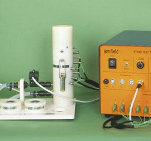
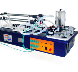
The Armfield HT10XC is a computer controlled service unit, which can be used in conjunction with a range of small-scale accessories for a wide range of demonstrations into the modes of heat transfer. The factors that affect heat transfer can be investigated and some of the practical problems associated with the transfer of heat can be clearly demonstrated. The heat transfer accessories may be individually connected to the HT10XC service unit, which provides the necessary electrical supplies and measurement facilities for investigation and comparison of the different heat transfer characteristics. A specific feature of the HT10XC is that it corporates the facilities and safety features to enable the accessories to be remotely controlled from an external computer, where this is appropriate. It will shut down safely in the event of a communications failure. With suitable (user provided) software, the equipment operated remotely, for instance over an intranet or even over the internet. All the facilities can also be accessed locally using the front panel controls and display.
The service unit is housed in a robust steel enclosure and designed for use on a bench or table. It provides control outputs to the accessories, and instrumentation inputs from the accessories.
Outputs:
- A stabilised, variable DC supply to the heater of the heat transfer accessory under evaluation
- Drive to flow-regulation valves on HT11C and HT12C
- Drive to the variable-speed air blowers used on HT14C and HT16C
Inputs and Instrumentation:
- Temperatures: (up to 10 off, dependant on accessory being used)
- Heater voltage: (All accessories except HT17)
- Heater current: (All accessories except HT17)
- Heat radiated: (HT13)
- Light radiated: (HT13)
- Air velocity: (HT14, HT14C, HT16, HT16C,HT19)
- Cooling water flowrate: (HT11C, HT12C, HT18C)
In manual mode, the outputs listed above are under control of potentiometers on the front panel of the unit. In remote mode the outputs to the accessories are controlled by the computer. A ‘Watchdog’ system is implemented in remote mode to ensure operator and equipment safety in event of a computer or communications failure.
In both modes the signals from the accessory can be shown on the front panel displays. Selector switches are used to select the chosen signal onto one of the two displays. These signals are also available on the USB interface for datalogging on the computer (even if the computer is not controlling the equipment).


